
The D331AT Sync & Gate Module is designed to deliver repetitive bursts of pulses. The bursts can last a set duration of time and can be repeated with a set repetition interval. If the duration time is set too long so that a second repetition command is requested during a burst, it is ignored, the requested burst duration is completed and an error is indicated.

The D332T Pulse Module provides the internal frequency and pulse width for the stimulation pulse. It provides 5 decades of control for the frequency and 4 decades for the pulse width using single turn controls and rotary switches.

This unit provides the controlled, power stimuli from a low impedance source needed for punctate stimulation or field stimulation of preparations in high impedance baths.
It provides control of stimulus strength up to 100V at 1Amp into loads of up to 0.01µF, with the voltage of the two channels independently controlled by single turn controls and range selector switches. Each channel has an on/off switch, stimulus indicator and an overload detector and automatically reset cutout.

The D334B Sync Module provides the front panel power switch, power-on/error LED, Pulse & Gate (EXT) In & Synchronisation (SYNC) sockets and a Single pulse button. The gating circuitry has been carefully designed so that only “whole” pulses are delivered to the preparations.
The D334B Sync Module provides the front panel power switch, power-on/fault bi-colour LED, synchronising sockets, single pulse button and indicator for the GATE waveform.
The D334B is generally used in applications where an external gating pulse from another device is used to activate the D332T Pulse module (via the Gate input) or when an externally derived pulse is used to define stimulus duration and frequency (via the Pulse input). In the latter scenario, a D332T would not be necessary.

The D335 Meter Module provides digital indication of the measured voltage or current of the stimulating waveform thus removing the need for an oscilloscope to measure these parameters.
The channel for measurement is selected from the front panel and the output is shown by a three digit LED display.
It has a rotary channel selector for channels 1 to 10 and a toggle switch for selecting the output parameter (mA, A or V) of interest.

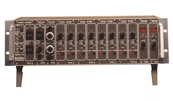
The D337 MultiStim Case and Power Supply is designed to accommodate up to 10 channels of stimulation (using D333/D343 Dual Stimulator modules) from either a common timing generator* or external timing signals. The motherboard distributes power to all modules, the timing pulse control and links the outputs to a common socket and optional digital current/voltage D335 Meter.
Stimulation modules can be fitted into the 10 right-hand bays, reserving the first 4 single width bays for timing, meter modules or blank panels.
This rack is fully enclosed and free standing on a table or bench using its front feet to tilt the case as necessary.

The single width D340 Count & Delay Module will allow a stimulus pulse of the same width set on the D332T PULSE to be added to the output train at a selected delay after a selected number of stimuli.
This will be found useful in determining Effective Refractory Period (ERP).

The right-hand side of the D341A Sync & Train Module provides control of the Gating function so that a set number of pulses can be delivered at an accurately set repetition interval. The left-hand side of the D341A Sync & Train Module has the functions of the D334B Sync. If the repetition time is set too short so that a second repetition command is requested during a burst, it is ignored; the requested Number of Pulses is completed and an error is indicated.

The D342 Dual Bistim Module provides a switching function allowing stimuli of alternating polarity to be presented to each of two preparations. It includes independent controls for stimulus polarity (Normal, Alternating or Reverse) of each channel as well as warning of a stimulus timing rate that is too-fast. The control and timing for the pulses is generated by selecting other modules from the D330 MultiStim range.
It should be noted that the unit works with mechanical relays that require a certain time to switch their polarity. The circuitry is designed so that the changeover command is taken (independently for each channel) from the end of each stimulus timing pulse so that the relay ‘moves’ when no stimulus is being applied. As with all mechanical devices, relays have a finite life. This is quoted as a minimum of 100,000,000 mechanical operations. If the relay was to ‘move’ whilst a stimulus was present, the contacts would wear-out much quicker than the mechanics. Therefore, the circuit will detect and warn the user if the ‘time-between’ stimuli pulses is less than 5ms. The user must ensure that this never happens.
 This unit provides two channels of high power, constant current stimuli needed for punctate or field stimulation of preparations in low impedance baths. The fully protected unit provides control of stimulus strength up to 500mA from 100V into low impedance baths with impedances as high as 200 ohms.
The output current of each channel is independently controlled by a single turn control and range selector switch. Each channel has an on/off switch, stimulus indicator and an overload/out-of-compliance indicator.
 The D344 Remote Module provides a front panel Power switch, power-on/fault bi-colour LED and independent control of each of the ten possible channels. These channels have an overriding ‘Enable’ control that enables the system to be instantly disabled using a single toggle switch.
The 15-pin ‘D’ connector provides pins for the independent control of each of the ten possible channels in a D337 Rack. It also has an external ‘Enable’ connection which, when selected on the toggle switch, acts as a simple ‘System-enable’. System earth is provided on the connector for cable shielding and logic zero volts and +5V is provided for a small amount of external logic if required.